Build guide for the Plaid-Pad
Solder the through hole parts
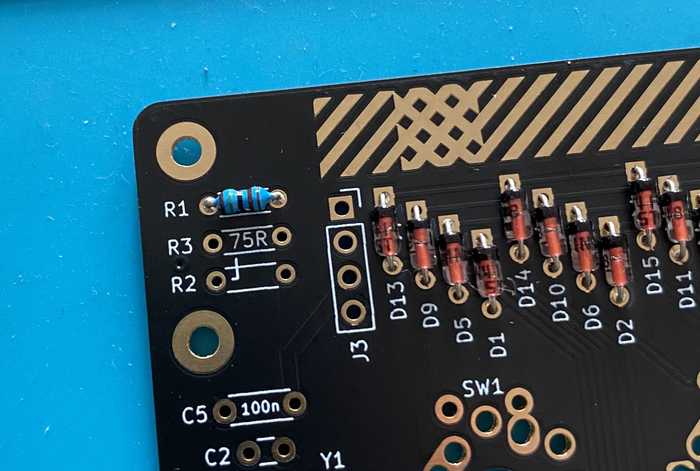
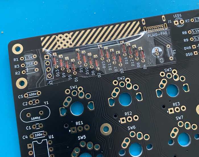
Diodes 1N4148 (D1-D16)
Diodes are polarized. The black line on the diode (cathode) must face the squared solder pad. The 1N4148 diodes look similar as Zener diodes - so make sure that you don't confuse both diodes.
You can use some tape, as show in the image, to hold the diodes in place and solder all in one pass.
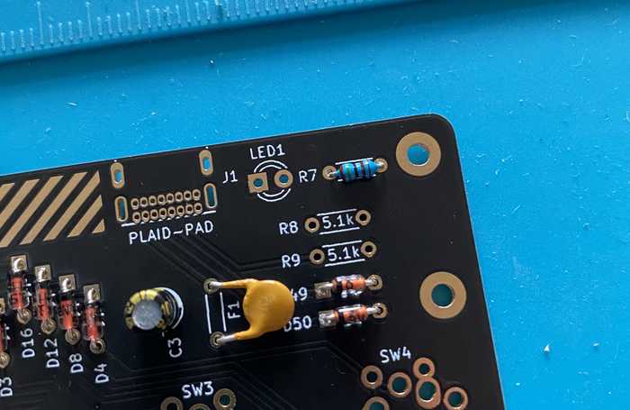
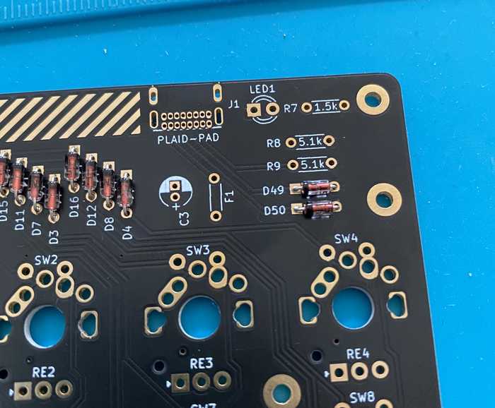
Zener diodes (D49, D50)
The diodes are polarized where the black line on the diode (cathode) must face the squared solder pad. The 1N4148 diodes look similar as Zener diodes - so make sure that you don't confuse both diodes.
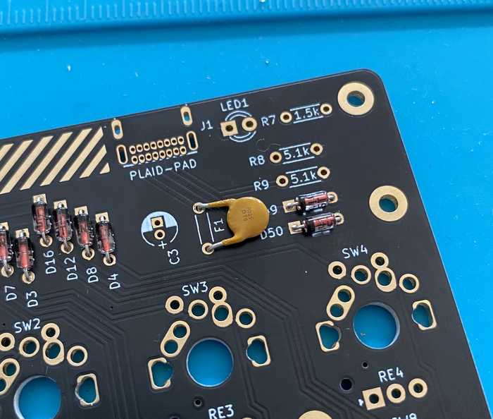
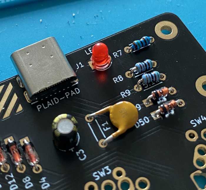
Resettable fuse (F1)
Attach and solder the fuse to F1. After soldering, bend the fuse like in the image.
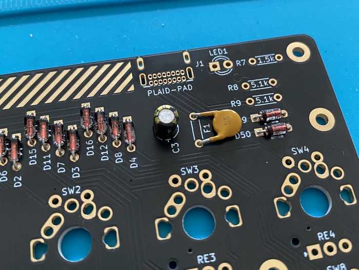
Electrolytic capacitor (C3)
The Electrolytic capacitor is polarized. The short leg is cathode which needs to be attached to the square pad on the PCB.
Resistors 1.5k Ohm (R1, R7)
Attach the resistors with following colors from left to right:
- brown, green, black, brown, brown
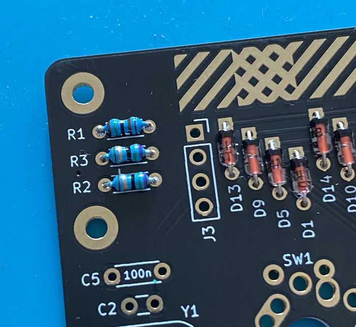
Resistors 75 Ohm (R2, R3)
Attach the resistors with following colors from left to right:
- brown, gold, black, green, purple
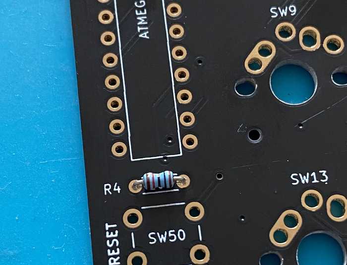
Resistors 10k Ohm (R4)
Attach the resistors with following colors from left to right:
- brown, black, black, red, brown
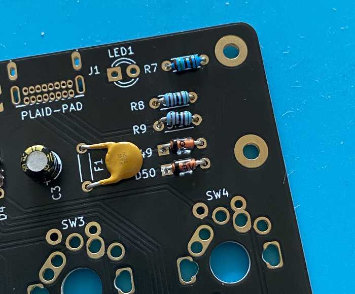
Resistors 5.1k Ohm (R8, R9)
Attach the resistors with following colors from left to right:
- green, brown, black, brown, brown
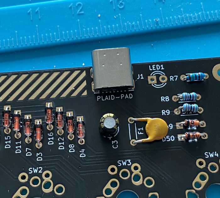
USB-C connector (J1)
Double check that there are no short cuts between the solder pads. A magnifier is handy for this task.
Optional: LED (LED1)
The LEDs are polarized. The short leg is the cathode which needs to be attached to the square pad on the PCB
LED1 indicates that the Plaid-Pad is powered and constantly on.
If you don't want a constant red light on your Plaid-Pad, don't solder this LED.
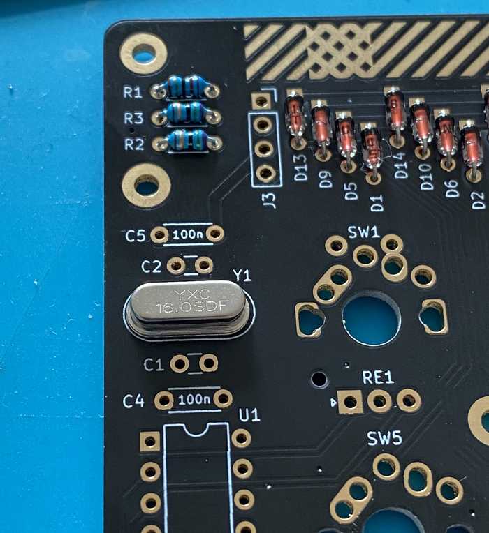
Crystal (Y1)
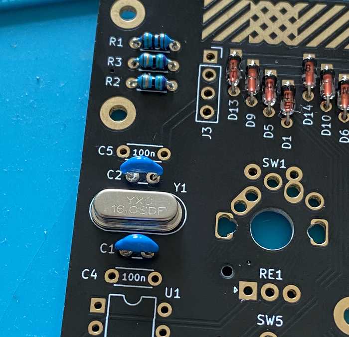
Capacitors 22pF (C1, C2)
They have a small pitch (2.5mm).
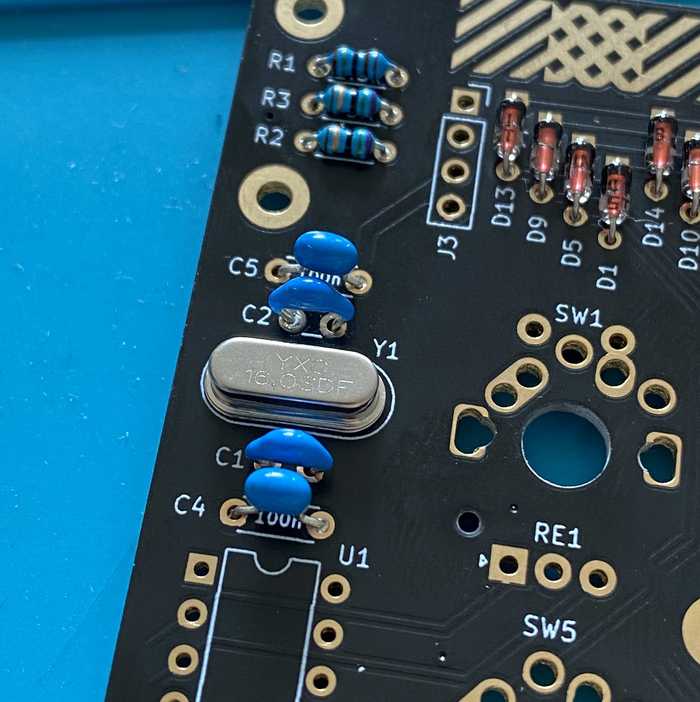
Capacitors 0.1uF (C4, C5)
These have a larger pitch of 5mm.
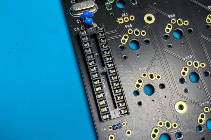
IC socket U1
The IC socket is polarized. Check the notch on the silk and the IC Socket.
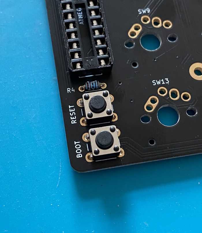
Tactile switch (SW50/RESET, SW51/BOOT)
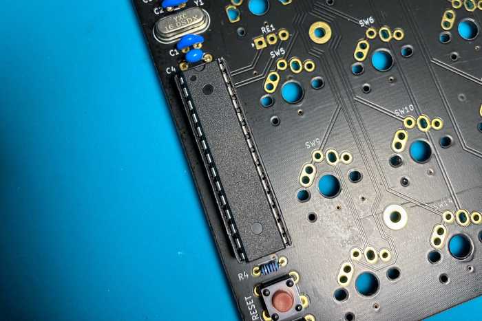
ATMEGA328p chip
The ATMEGA328 has to be attached in a specific direction. Check the notch on the chip and IC Socket - they need to match. Here, the notch faces the crystal at Y1.
OLED display (SSD1306)
Add isolation tape to the back of the OLED, to protect the components for shorts.
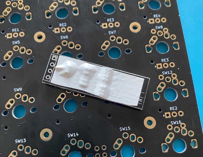
Place the OLED like on the image and solder it from the bottom to the PCB.
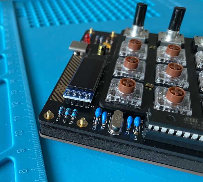
Check list before connecting USB
- No short cuts on the USB-C connector pads
- Direction of polarized and directional components is correct (ATMEGA328p, diode, resettable fuse, electrolytic capacitor, LEDs)
- Resistors with correct values are attached to the target locations
Test
Bootloader and Firmware (VIA keymap) are already on the ATmega328P chip.
Everything should work after soldering.
Connect the Plaid-Pad to your computer and open the QMK-Test-Site.
Check whether all switches will work. To do so, short the solder pads with tweezers.
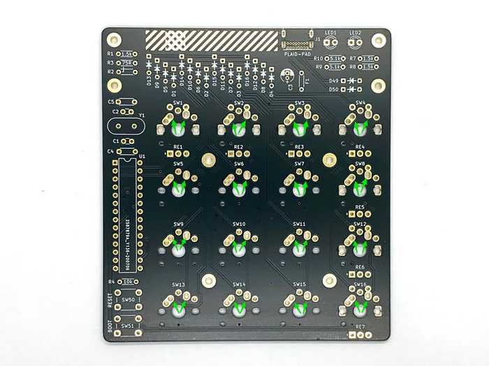
Optional Mill-Max holtites
The Plaid-Pad supports Mill-Max 0305 Holtites. If these are installed, you can Hotswap the switches (change without soldering).
Put the holtite in the related holes.
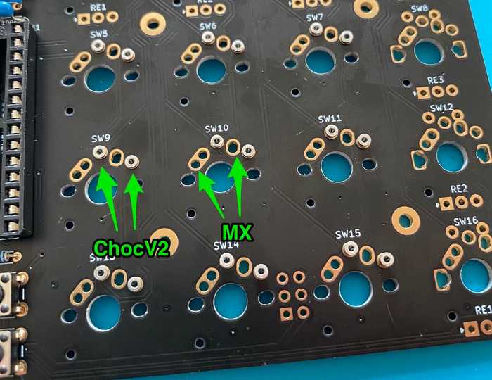
Install all switches to the top plate. Check that all switch pins are straight and press the top plate with switches on the PCB with the holtites.
Pay attention that no solder flows into the holtite.
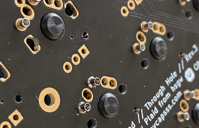
Case assembly
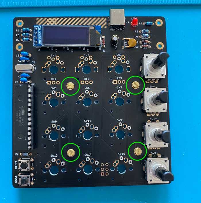
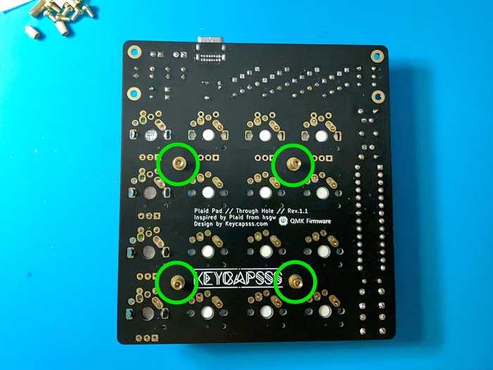
Before you solder the switches, attach the 4x 5mm spacer to the pcb with the M2x4mm screws.
Don't solder the rotary encoder yet.
Attach all switches to the top plate and place (not solder) the desired amount of the rotary encoder on the pcb (more information about rotary encoder placement).
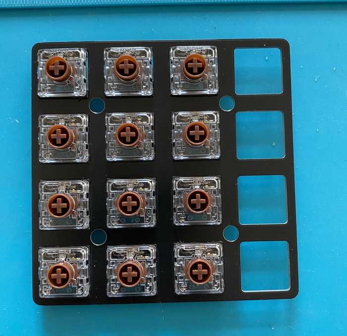
This way the rotary encoder have room to move and fit perfect into the top plate cutout.
Rotary encoder and Choc (low profile) switches (skip if you use MX switches)
If you use Choc (low profile) switches, you have to bend the 5 pins of the rotary encoder with a pliers, to fit into the top plate.
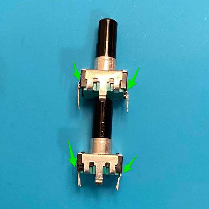
Put the top plate with the switches on the front side of the pcb.
Solder the switches and rotary encoder from the bottom side.
Ensure that there is no gap between the switch bottom and the pcb. Same for the encoder.
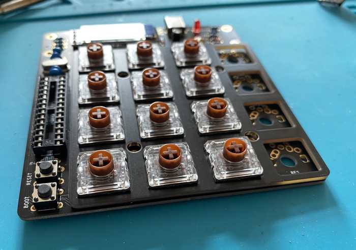
Screw the 4x 5mm spacer at the upper part of the bottom plate. Use the 12mm (10mm) screws for it.
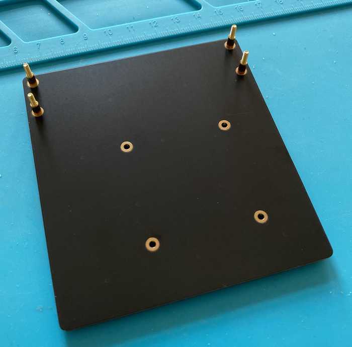
Optional: Put the dampening foam on the bottom plate.
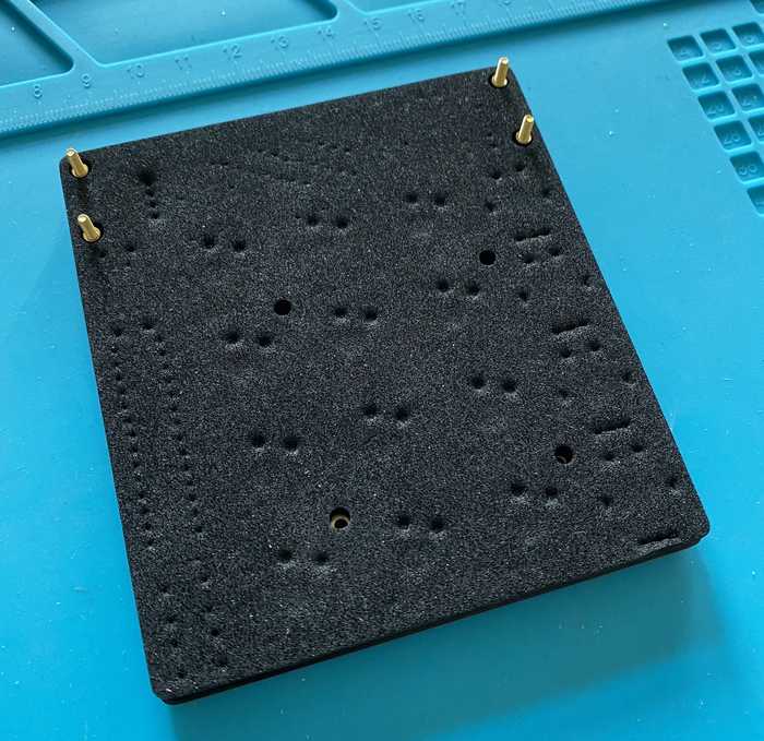
Put the assembled top plate with the switches and pcb on the bottom plate.
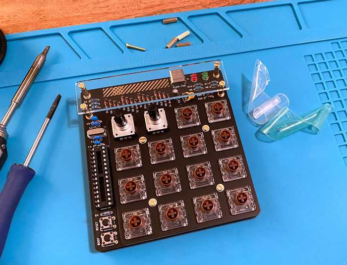
Screw the 4x 10mm spacer for the guard plate on 12mm (10mm) prominent screws from below. Remove the protection film on both sides from the acrylic guard plate. Fix the acrylic guard plate and the pcb with the 4mm screws.
Don't overtighten the screws, the acrylic plate can break.
Put the rubber feeds on the back of the Plaid-Pad.
The assembly is done. 🥳
You can change the keymap with VIA (no rotary encoder support), VIAL (with rotary encoder support), or change the QMK keymap file and reflash the firmware.
How to flash the firmware
QMK with VIAL support (support for rotary encoder)
Plaid-Pad Kit's Rev3 shipped with preflashed VIAL firmware.
If you have a Rev2 Plaid-Pad, or want to re-flash the VIAL firmware again, you can find a compiled firmware file here (Rev2, Rev3)
- Flash pre-compiled firmware on the Plaid-Pad with QMK Toolbox (How to enter Bootloader Mode).
- Download the VIAL software from here
- Connect the Plaid-Pad to the computer with a USB cable (Reconnect after flashing the firmware)
- Open VIAL and change the keymap to your needs (automatic save)
QMK with VIA support (no rotary encoder support)
To use VIA, compile the VIA Keymap with the following command and flash it with QMK Toolbox on the Plaid-Pad (enter Bootloader Mode).
qmk compile -kb keycapsss/plaid_pad -km via- Download the VIA software from here
- Connect the Plaid-Pad to the computer with a USB cable
- Open VIA, switch to the
CONFIGUREtab and change the keymap to your needs (automatic save)
The current VIA version can't change the rotary encoder function.
QMK Default Keymap
Make example for this keyboard (after setting up your build environment):
make keycapsss/plaid_pad:defaultor
qmk compile -kb keycapsss/plaid_pad -km defaultFlashing example for this keyboard:
make keycapsss/plaid_pad:default:flashor
qmk flash -kb keycapsss/plaid_pad -km defaultSee the build environment setup and the make instructions for more information. Brand new to QMK? Start with the Complete Newbees Guide.
You can find the rotary encoder code here.
Bootloader
- same
usbasploaderas used for Plaid (Instructions, Repository)
Enter Bootloader Mode (to flash a new firmware)
- Plug in the USB cable
- Push and hold RESET switch
- Push and hold BOOT switch
- Release RESET switch
- Release BOOT switch
alternative method:
- Unplug the USB cable
- Hold down the BOOT switch
- Plug in the USB cable
- Release the BOOT switch
alternative method (Bootmagic Lite):
- Unplug the USB cable
- Hold down the most top left key
- Plug in the USB cable
- Release the most top left key
If you succeed to enter bootloader mode, you can see usbasp in device manager, or *** USBAsp device connected in QMK Toolbox.
